
Product Description
Product Description
COUPLINGS
| HRC | FCL | Chain coupling | GE | L | NM | MH | Torque limiter |
| HRC 70B | FCL90 | KC4012 | GE14 | L050 | NM50 | MH45 | TL250-2 |
| HRC 70F | FCL100 | KC4014 | GE19 | L070 | NM67 | MH55 | TL250-1 |
| HRC 70H | FCL112 | KC4016 | GE24 | L075 | NM82 | MH65 | TL350-2 |
| HRC 90B | FCL125 | KC5014 | GE28 | L090 | NM97 | MH80 | TL350-1 |
| HRC 90F | FCL140 | KC5016 | GE38 | L095 | NM112 | MH90 | TL500-2 |
| HRC 90H | FCL160 | KC6018 | GE42 | L099 | NM128 | MH115 | TL500-1 |
| HRC 110B | FCL180 | KC6571 | GE48 | L100 | NM148 | MH130 | TL700-2 |
| HRC 110F | FCL200 | KC6571 | GE55 | L110 | NM168 | MH145 | TL700-1 |
| HRC 110H | FCL224 | KC8018 | GE65 | L150 | NM194 | MH175 | |
| HRC 130B | FCL250 | KC8571 | GE75 | L190 | NM214 | MH200 | |
| HRC 130F | FCL280 | KC8571 | GE90 | L225 | |||
| HRC 130H | FCL315 | KC1571 | |||||
| HRC 150B | FCL355 | KC12018 | |||||
| HRC 150F | FCL400 | KC12571 | |||||
| HRC 150H | FCL450 | ||||||
| HRC 180B | FCL560 | ||||||
| HRC 180F | FCL630 | ||||||
| HRC 180H | |||||||
| HRC 230B | |||||||
| HRC 230F | |||||||
| HRC 230H | |||||||
| HRC 280B | |||||||
| HRC 280F | |||||||
| HRC 280H |
Catalogue
Workshop
Lots of coupling in stock
FAQ
Q1: Are you trading company or manufacturer ?
A: We are factory.
Q2: How long is your delivery time and shipment?
1.Sample Lead-times: 10-20 days.
2.Production Lead-times: 30-45 days after order confirmed.
Q3: What is your advantages?
1. The most competitive price and good quality.
2. Perfect technical engineers give you the best support.
3. OEM is available.
/* March 10, 2571 17:59:20 */!function(){function s(e,r){var a,o={};try{e&&e.split(“,”).forEach(function(e,t){e&&(a=e.match(/(.*?):(.*)$/))&&1
| Standard Or Nonstandard: | Standard |
|---|---|
| Structure: | Flexible |
| Material: | Cast Iron |
| Type Name: | FCL |
| Origin: | Zhejiang |
| Customization: |
Available
| Customized Request |
|---|
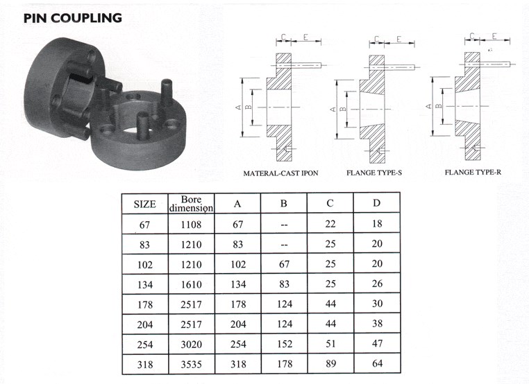
What Are the Maintenance Requirements for Pin Couplings?
Pin couplings are known for their simplicity and ease of maintenance. Regular maintenance helps ensure the longevity and optimal performance of pin couplings in various mechanical systems. Here are the key maintenance requirements for pin couplings:
- Lubrication: Most pin couplings require periodic lubrication to reduce friction between the pins and the coupling hubs. Lubrication helps prevent wear and corrosion, ensuring smooth operation.
- Inspection: Regular visual inspections are essential to identify any signs of wear, misalignment, or damage. Inspecting the pins, coupling hubs, and surrounding components can help detect potential issues early on.
- Torque Check: It is crucial to periodically check and retighten the bolts or screws that secure the coupling to the shafts. Loose fasteners can lead to misalignment and coupling failure.
- Alignment: Proper shaft alignment is critical for the effective functioning of pin couplings. Regularly check and adjust the alignment if necessary to minimize wear and vibrations.
- Environmental Protection: In harsh environments or corrosive conditions, take measures to protect the pin coupling from contaminants or chemicals that could cause damage.
- Replacement of Worn Components: When any of the coupling components, such as pins or hubs, show signs of significant wear, they should be replaced promptly to prevent further damage.
It is important to follow the manufacturer’s maintenance guidelines and recommendations for the specific type of pin coupling used in the application. Regular maintenance not only ensures the smooth operation of the coupling but also helps prevent unexpected breakdowns and reduces the risk of costly downtime. Proper maintenance can extend the service life of pin couplings and contribute to the overall reliability of the connected equipment.
How Does a Pin Coupling Handle Angular, Parallel, and Axial Misalignment?
A pin coupling is designed to handle different types of misalignment, including angular, parallel, and axial misalignment. The unique construction of pin couplings allows them to accommodate these misalignments without compromising the efficiency and performance of the connected equipment.
1. Angular Misalignment: Angular misalignment occurs when the axes of the driving and driven shafts are not parallel but intersect at an angle. Pin couplings can tolerate angular misalignment because of their flexible and floating pin design. The two coupling halves are connected by a series of pins, which can pivot and move within the pin holes. This flexibility allows the coupling to bend slightly, adjusting to the angle of misalignment between the shafts.
2. Parallel Misalignment: Parallel misalignment happens when the axes of the driving and driven shafts are parallel, but they are laterally displaced from each other. Pin couplings can handle parallel misalignment to some extent due to the floating nature of the pins. The pins can move laterally within the pin holes, allowing the coupling to adapt to the offset between the shafts.
3. Axial Misalignment: Axial misalignment occurs when there is a linear displacement along the axis of one shaft concerning the other. While pin couplings primarily focus on handling angular and parallel misalignment, they may offer limited axial misalignment capabilities. The floating pins provide a small degree of axial movement, but excessive axial misalignment is best avoided to prevent additional stresses on the coupling.
It is important to note that while pin couplings can accommodate some degree of misalignment, excessive misalignment should be avoided to prevent premature wear and potential failure of the coupling and connected equipment. Regular inspection and maintenance can help identify and address any misalignment issues, ensuring the optimal performance and longevity of the pin coupling in power transmission applications.
Can Pin Couplings Handle Misalignment Between Shafts?
Yes, pin couplings are designed to accommodate a certain degree of misalignment between shafts in rotating machinery. They are considered flexible couplings, which means they can provide some degree of angular, parallel, and axial misalignment capability.
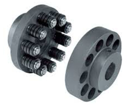
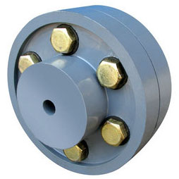
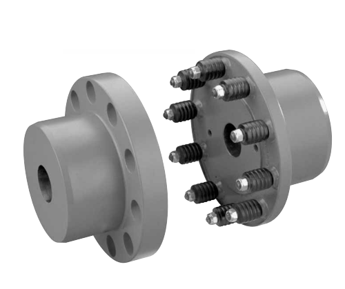
Pin couplings typically consist of two hubs, each connected to a shaft, and a central sleeve with pins that transmit torque between the hubs. The pins allow for a limited range of movement, which helps to compensate for slight misalignments between the shafts.
The angular misalignment capacity of a pin coupling is achieved through the bending of the pins. When the shafts are misaligned at an angle, the pins on one side of the coupling experience bending while those on the opposite side are in tension. The pins are designed to withstand these bending and tension forces within their elastic limits, ensuring proper functioning and longevity of the coupling.
Similarly, the pins can accommodate parallel misalignment by sliding within the pin holes of the coupling’s central sleeve. This sliding action allows the hubs to move slightly relative to each other, compensating for any offset between the shafts.
However, it is essential to note that pin couplings have limitations in terms of the amount of misalignment they can handle. Excessive misalignment beyond their specified limits can lead to increased wear on the pins and other coupling components, reducing the coupling’s effectiveness and potentially causing premature failure.
While pin couplings are suitable for applications with moderate misalignment requirements, they may not be the best choice for applications with significant misalignment or where precise alignment is critical. In such cases, more flexible couplings like gear or elastomeric couplings may be more appropriate.
Overall, when considering the use of pin couplings, it is essential to carefully evaluate the specific misalignment requirements of the application and select a coupling that can adequately accommodate those misalignments while ensuring reliable and efficient power transmission.


editor by CX 2024-02-24